Mass Flow Setting
Calibrate the Mass Flow Meter and Pressure Transducers.
1. Follow the procedures in “Calibration of Mass Flow Meter and Pressure Transducers”
2. Continue with “Adjust the Mass Flow and Ballast Tank Valves,”
Adjust the Mass Flow and Ballast Tank Valves
Procedure for reduction of vibrations associated with the compressed gas.
1. Remove the housing surrounding the CCC.
2. Close the ballast tank valve finger, see Figure 10, tight then reopen the valve 5 turns.
3. Begin cryogenic operations, follow the procedure for “Routine Operation,”.
4. Wait for probe to reach 25K before proceeding.
5. Operate the system with the probe cold for 3 hours before continuing.
6. Open (fully) the mass flow valve (located below the Inlet transducer), see Figure 10.
7. Wait until the mass flow reaches its maximum value on the mass flow meter of 39 – 46 SLM (std. liters/minute).
8. Record the maximum mass flow (MassFlowMax).
9. Close the mass flow valve until the reading on the mass flow meter is:
10. Adjust the ballast tank valve until the mass flow is at 26 SLM (reaching equilibrium may take time).

Calibration of Mass Flow Meter and Pressure Transducers
The calibration of the mass flow meters and the pressure transducers are unique to each CCC / CryoBay combination.
1. Turn on the power to the CryoBay and compressor, and allow them to warm up for 15 minutes.
2. With the CCC not running, the readings should be:
a. Pressure Inlet = Pressure Outlet = 0
b. Mass flow = 0, same as on meter at CCC.
If meter is not zero, the meter may need calibration at the CCC.
c. If the values are off, they will need to be calibrated. Note the values.
3. Exit the CryoBay Monitor program.
4. Click on the Measurement and Automation Explorer icon on the desktop.
5. Click on Scales select a scale for the calibration:
• Inlet scale
• Exhaust scale
• Mass Flow Scale
6. Right click on Scales and select Properties.
A graph will be displayed, along with the straight line equation y=mx+b.
7. Adjust the b value as necessary, and add the negative of the reading on the monitor.
Click OK
8. Repeat step 5 through step 7 for each scale.
9. Click on Tools from the menu bar.
10. Select NI-DAQ Configuration
11. Select Save configuration as
12. Choose file name (or create new one)
a. Current file name:
c:\Program_files\cryobaymonitor<current software version number>\V3.0.daq
b. It may be desirable to save it to the desktop.
13. Click on Tools from the menu bar
14. Select NI-DAQ Configuration.
15. Select Set active configuration
16. Select the daq file to be accessed by the CryoBay Monitor. This should be the configuration just saved.
17. Close the Measurement and Automation Explorer.
This window must be closed to run CryoBay Monitor.
Routine Operation
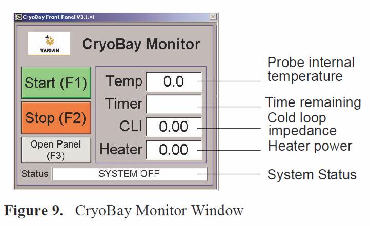
The CryoBay monitor program, see Figure 9, and controls following start up and cryogenic operations processes:.
• Purging and repressurizing of the system — gas escaping will be heard during this process, this is normal
• Starting the CCC (He Refrigerator)
• Cooling down the probe
• Regulating the probe internal temperature at the set point.
• Monitor and control all cryogenic functions and systems.
Start the cryogenic process as follows:
1. Start the CryoBay monitor program.
2. Click the Start button or press F1 on the keyboard to start cryogenic operation.
The CryoBay monitor on the PC, see Figure 9, and the CryoClient on the spectrometer workstation display the following information:
• Probe internal temperature
• Time remaining in the cool down process
• Cold loop impedance
• Heater power
• System status and faults
All control functions and parameter adjustments are accomplished through the CryoBay monitor window running on the PC in the CryoBay. The CyroClient running on the spectrometer workstation only reports status.
3. Allow the system to equilibrate.
Under normal operating conditions the system will be ready for use in 4 hours.
Optimal system stability is achieved when the system is allowed to equilibrate overnight. The ion pump will turn on when the system status changes to READY.

